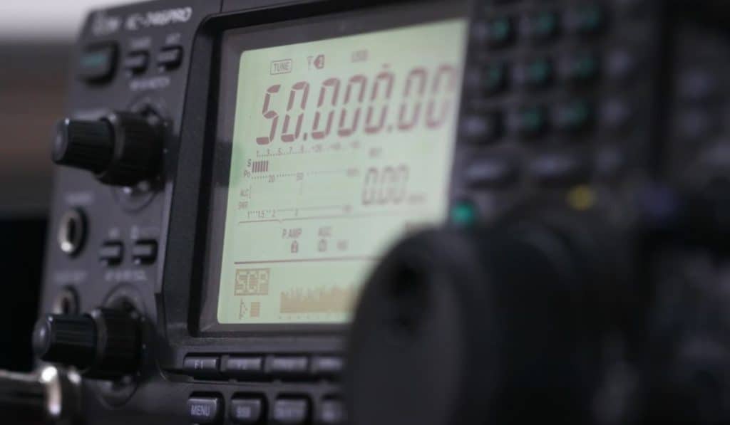
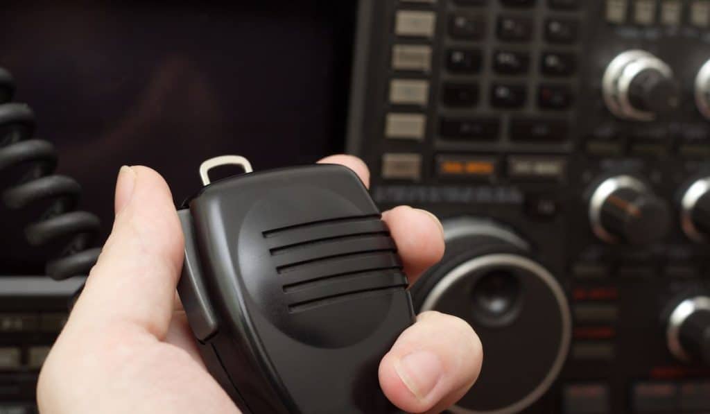
Ham radios also known as amateur radios, are devices used to transmit and receive radio waves broadcast for non-commercial use.

Ham radio operators are known as Hams. Hams do this mainly as a hobby since there are no monetary gains but, in the process, can positively impact a lot of lives by building meaningful groups that include other hams, radio enthusiasts; they also share critical information that has led to several important innovations over the years.
The contribution that hams radio has had over society, especially during periods of natural disasters when most communication is down is huge, to say the least.
But how do these handy pieces of equipment work to share and send information from one point to another?
In our definitive guide into the amateur radio hobby, we covered most of the basics things that you need to know as a beginner ham (you can visit that complete article to learn more). However, in this article, we are going to get a bit technical and look at how ham radio works to convey information.
Read our complete guide to Ham Radio here!
How Ham Radio Works
The basics
Ham radios use radio waves to broadcast, transmit and receive information from one person to another or a group of other people.
Radio waves make up the lower part of the electromagnetic spectrum. They are essentially the lower frequencies on this spectrum and, therefore, can also be classified as electromagnetic waves.
As you can tell from the name, electromagnetic waves use a combination of both electricity and magnetism. The waves are generated from alternating/oscillating electric and magnetic fields and travel outwards from their source.

However, Hams do not use the entire radio waves spectrum. Since the frequencies have to be shared by other people that include cell phone users, the military, the police, the internet, and so on; only a small portion of the frequencies are allocated to ham radio operators.
Radio frequencies range from as low as 3KHz (kilohertz) to as high as 300GHz (Gigahertz). Hertz is the unit used to measure frequency or the number of oscillations per second.
Hams are only allowed to use frequencies from 1.6 MHz to 1240 MHZ. However, even with this allocation, Hams usually use HF (high frequency), VHF (very high frequency), and UHF (ultra-high frequency) bands.
- High frequencies or HF frequencies range from 3 to 30 Megahertz which range from 80-meter to 10-meter bands.
- VHF or Very High Frequencies range from 30 to 300 Megahertz which use the 6-meter and 2-meter bands.
- UHF or Ultra-high frequencies range from 300 Megahertz to 3 Gigahertz and are known as the 70-centimeter bands.
You need a license to broadcast on the ham radio frequencies, but you can freely listen to the transmissions without legal repercussions. Listening can be done by having a receiver only piece of equipment (Rx).
Also, depending on the type of license you have, you can only use the frequency band stipulated by the terms of the license. For example, to use some of the HF bands you will need a General license, and to broadcast in all frequency bands, you will need an Amateur Extra class license.
You also need two essential pieces of equipment to be a Ham operator, namely:
- A transmitter (Tx)
- A receiver (Rx)
The transmitter and receiver can also be combined into one to form what is known as a transceiver (Tx/Rx). A transceiver can be a portable handheld device or HT (handie talkie) or may be bulkier and less portable.
Either way, you need to know how both the transmitter and receiver work to have a better understanding of amateur radio inner workings.
The Transmitter Stage
Transmitters are devices responsible for generating radio sine waves that are used to broadcast the intended information. This information can be a voice note, a video, a morse code, or any other type of ham message that you wish to relay.
They do this with the help of 5 main components which are:
- A power supply
- An oscillator
- A modulator
- An amplifier
- An antenna
To make it simple for you to understand as we move forward, I will use a simple flow diagram to show you how the transmission is generated.
- Power Supply (provides the wattage needed)
- Oscillator (creates an alternating current/AC which is used as the carrier wave)
- Modulator (encodes the information to be relayed to the carrier wave)
- Amplifier (increases the modulated carrier waves’ gain/amplifies it)
- Antenna (takes the modulated wave which is essential AC current-carrying information and converts it into an electromagnetic wave with the same frequency as the modulated carrier wave
Power supply
The power supply can range from simple rechargeable batteries in handheld transmitters to larger power supply units (PSUs) in more complex setups that can be fitted into a vehicle or an amateur radio room.
- 13.8V DC Power Supply for Ham/CB Radio
- 30A MaxCurrent Output
- DC 9-15V adjustable
- Cigarette Plug + Noise offset
- 1 Year USA warranty
This power source should be able to supply enough wattage to the transmitter depending on its rating.
The oscillator
Oscillators use power from the power supply to generate a carrier wave by alternating the current back and forth with the help of an inductor and a capacitor.
So, basically what happens is that the capacitor gets charged up by the incoming current and starts releasing the charge once it reaches full capacity.
As the capacitor discharges, the inductor charges the other plate on the capacitor using a magnetic field (a capacitor is made up of two plates and an insulator, at the basic level). The inductor’s magnetic field collapses and by the time this happens, the capacitor will be fully charged again.
This happens continuously many times a second as long as the oscillator receives a steady power supply and, in the process, generates an oscillating current (sine wave) also known as an alternating current or AC.
The generated current is used as the carrier wave.
Modulator
The modulator is responsible for encoding (adding) the information into the carrier wave that was generated by the oscillator.
There are two main types of modulation in ham radio and that is;
- Frequency modulation/FM; This is where the carrier wave’s frequency is modified/modulated depending on the information you intend to broadcast. For example, if you plan to transmit a voice message, a diaphragm inside the microphone will vibrate in accordance with your voice and generate a current. This current will be a continuous sine wave that can be added to the carrier wave whose frequency will vary per the sound wave.
- Single sideband/SSB modulation– SSB modulation is a type of Amplitude modulation/AM (the sine wave’s amplitude is varied in accordance with the information being encoded). However, with SSB modulation, some of the unnecessary components in the modulated AM wave are removed to make the wave more efficient hence reducing its bandwidth (size of the signal). What you are left with is a wave with one sideband. So, instead of a “hills and troughs” wave you are left with only hills.
Frequency modulation is widely used as opposed to SSB modulation since it is less susceptible to interference and noise and has a higher quality transmission. However, FM is less efficient when compared to SSB and, therefore, SSB is used in cases where the information needs to be transmitted for longer distances but will a very stable receiver.
Amplifier
The amplifier in the transmission stage is used to step up the voltage of the modulated signal to make it powerful enough for transmission.
This is done with the use of transistors. Transistors are 3-pin semiconductors (diodes) that can increase the strength of the signal and also rectify it.
The antenna
This is the last stage of transmission where the amplified modulated signal is taken and converted into electromagnetic waves.
The electromagnetic waves are generated through electromagnetic induction since the incoming signal will be alternating many times a second.
These alternating currents cause the electrons in the antenna to move back and forth generating an electromagnetic field that is radiated outwards through the atmosphere slightly under the speed of light in a vacuum.
The speed of light in the air is 299,792,458 meters per second which is 1.0003 times slower than the speed in a vacuum which is 300,000,000 meters per second.
Once the radio waves are radiated, they can travel directly to a receiver if it is in the line of sight, to a ham repeater which takes the signal and makes it powerful enough for long-distance transmission, or to the ionosphere which is the charged section of the earth’s atmosphere where they are reflected to other parts of the world for even longer transmissions.
The ham radio waves can also bounce off ionized meteors, the moon, the aurora borealis, or use amateur radio satellite repeaters.
The Receiver Stage
This is where the transmitted ham signals are received by another ham or radio enthusiast in your region or other parts of the world, decoded, and converted into a form you can understand (visual or audio).
And just like in the case of a transmitter, some components work in tandem to make a receiver operate as intended. These components are:
- A power supply
- An antenna
- An RF preamplifier
- A tuner circuit
- A demodulator or detector
- An amplifier
- Power Supply (provides the wattage needed)
- Antenna (Intercepts the existing radio waves and convert them into low voltage alternating current)
- RF preamplifier (makes the intercepted signals slightly powerful by raising their voltage level)
- Tuner (Separates the intended frequencies from a pool of other frequencies)
- Demodulator (takes the signal and extracts/decodes the encoded information from the carrier wave)
- Amplifier (Makes the signal strong enough for the speakers)
There may also be a DSP (digital signal processor) in the receiver that is essential for extracting digital information from the carrier wave. Digital ham receivers will have a DSP in place of an analog demodulation circuit.
Other receivers/transceivers also have a screen to display messages and other visual digital information.
Power supply
Provides the power that is needed by the receiver system. This will be the same power supply as the transmitter if you are using a transceiver.
Antenna
Works in reverse fashion to the transmitter antenna by intercepting radio waves from the atmosphere which cause the electrons in the antenna to vibrate creating an electrical current.
The preamplifier
This is the part where the voltage in the intercepted RF signals is stepped up/pre-amplified slightly before being sent to the tuner.
The preamplifier name is used because it is used to amplify the signal before the actual power amplification takes place later in this stage.

The tuner
This is where the frequency you intend to listen to is separated from other radio frequencies using an RF filter.
RF filters work by using both capacitors and inductors just like the oscillator in the transmission stage. However, in this case, variable capacitors or variable inductors are used.
When tuning your ham radio to a certain radio frequency what you are doing is varying the capacitance and equalizing the inductive and capacitive reactance which, in turn, filters out the unwanted frequencies (higher or lower frequencies) and only allows the intended signals (resonant frequency) to pass through.
This process of equalizing the capacitive and inductive reactance is known as resonance.
Demodulator/detector
The demodulator or a detector is a complex circuit that takes the resonant frequency and extracts the information that was modulated to the carrier wave in the transmission stage.
Depending on how the information was modulated, the right demodulator will be needed to separate the data from the carrier wave.
In the case of SSB, the carrier wave will first need to be reconstructed to its original AM form before the information is extracted using a diode circuitry.
The demodulation is a very complex engineering process that is beyond the scope of this article but on a basic level that is what it does and what you should know if you are a ham operator or an aspiring ham.
The amplifier
The demodulated signal is sent to an amplifier that is responsible for making it powerful enough to be played back by the speakers by using transistors that step up the signal’s voltage using power drawn from the power supply.
Without the power amplifier, the sound would be so faint to be picked up by your ears.
It is important to keep in mind that amplifiers need to draw power from the power source since they cannot create power out of thin air.
In Conclusion
As you have seen amateur radio may seem like simple devices but there are a lot of complex processes that are involved in the transmission and reception of ham frequencies.
These processes take place in very little time, usually, microseconds denoted as µs. The scope of a microsecond is beyond our cognitive abilities and that is what makes radio so interesting.
How ham radio works and how fast it works coupled with the endless possibilities that you can achieve with its use, some of it being lifesaving, makes amateur radio even more interesting to learn and operate.
Also understanding how ham radio works will come in handy when it comes to taking your ham exam to make you a licensed operator. So, take your time to understand the various concepts and use other study guides during preparation.


